Test Rig for Water Softener Valves.
In normal use Domestic Water Softener Valves perform a complex sequence of
water flow reversals though the brining chamber to regenerate and flush the water
softener. This sequence normally takes an hour or two, and occurs only when a
certain amount of water has been softened. The requirement was to perform a full
test on every valve produced; but to only take a few minutes to perform test
measurements at the five critical valve positions.
This system is designed to test the valves on the production line, after the
mechanical assembly has been completed, but prior to fitting the valves own
electronics and motor. Assembly is a complex process involving numerous small
components and seals.
The test rig comprises a fixture onto which the valve to be tested is clamped. This
fixture has various water connections to the valve under test, which are made
automatically. A large electric pump draws water from a collection tank and
circulates it through the valve at up to 100 litres/minute and pressures of up to 2
Bar. Pressure and flow transducers measure the water pressures and flow rates
passing through the valve and also measure the vacuum generated by a venturi
suction section, which is built into the valve. The valves own turbine meter and
photo-electric position sensor are also monitored by the test rig.
A 24vDC motor is mounted to the side of the fixture with an external gears to allow
it engage with the plastic drive gear on the valve. The system is thus able to drive
the valve under test to all it’s operating positions and measure flow rates and
pressures at each position. These measurements are compared with pre-set levels
and a valve is only passed if it meets all the specified flows and pressures.
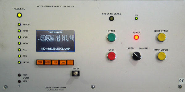
The control system comprises a dedicated real-time control computer, housed in a
metal enclosure, on the front of which are various operator controls, together with
function keys and an LCD screen and indicator LEDs. The screen is used to display
the operating parameters and production data. The enclosure also houses the
control computer and measurement interfaces. A separate enclosure houses the
power supplies for the computer and transducers.
The system enables the various configuration and test definition parameters to be
entered using a simple menu structure. This data is stored in battery-backed
memory and is not lost if the system is powered down. The control computer used
in the system is programmed in a high-level multi-tasking control language, which
is an object-orientated real-time control language similar to PASCAL.
The computer has opto-isolated interfaces to the various transducers and solenoid
valves, and two RS232 serial links; one for the printer which produces Serial
Number Labels, the other enables a portable computer to be periodically connected
to download a Test History File and to record the Configuration Parameters.
Two systems have now been supplied. The first was installed in the UK in 2002 and
dramatically reduced the number of service visits required by field service
engineers, as assembly faults are now trapped on the production line.
The other was installed in 2004 on a production line in China. Software updates
were made at various times to add extra facilities at the request of the customer;
the latest update being in 2010.